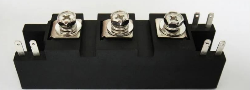
Using the thyristor, can also achieve controllable full wave rectification, including single phase and three phase, today simply talk about the single phase full wave controllable circuit.
The circuit diagram of single-phase controlled bridge rectifier is basically the same as that of single-phase bridge rectifier, except that the diodes on two of the bridge arms are replaced by thyristors.
Thyristors V1 and V2 are used on the upper bridge arm, while diodes V3 and V4 are used on the lower bridge arm.
The circuit is mainly composed of two parts, one is the rectifier circuit, called the main circuit in the picture, and the other is the trigger circuit.
The thyristor can only be turned on when the anode and gate apply forward voltage, so it is necessary to have a trigger pulse that changes the thyristor turn on.
When the v2 waveform is in the positive half axis, V1 and V3 bear the positive voltage. If there is no gate voltage at this time, the thyristor V1 will not turn on. Only when the gate voltage VG comes (when triggered), it will turn on. At this time, through V1, RL, V3 form a loop, the load RL will have dc voltage at both ends.
 When V2 passes zero, the thyristor automatically shuts off and waits for the next trigger.
When v2 waveform is in negative half axis, V2 and V4 bear positive voltage. In the negative half axis, if the trigger voltage VG comes, the thyristor V2 is turned on. At this time, the circuit is formed through V2, RL and V4.
As mentioned above, the output voltage can be adjusted by adjusting the conduction Angle of the thyristor, but no matter how it is adjusted, it will not exceed 0.9 V2. V2 is the effective value of the secondary voltage of the transformer. Therefore, the thyristor voltage regulating range is 0-0.9 V2.
The Angle corresponding to α in the figure is the trigger Angle, that is, the Angle corresponding to the starting time of the trigger, θ is the conduction Angle, by changing the size of θ, you can adjust the output of the DC voltage.
VL = 0.9 v2 (1 + cosine theta) / 2
Knowing the average dc voltage VL, the average DC current can be obtained by Ohm's law, IL=VL/RL, and the current through each pipe fitting is IL/2.
In the selection of thyristor, also need to consider the reverse maximum voltage, this value is usually based on the transformer secondary voltage maximum to consider, to choose 1.5-2 times the instantaneous voltage maximum.
In order to achieve the purpose of controlled rectifier, a trigger signal with adjustable phase should be added to the gate of the thyristor to adjust the output voltage.
The circuit that provides the trigger signal is called the trigger circuit. Finally, this trigger circuit is described.
After the thyristor is triggered to turn on, the trigger signal will not work, so this signal is usually a transient transient pulse voltage signal with a short acting time. In order to ensure the reliable operation of the thyristor, the trigger signal should have a certain amplitude (4 ~ 10V) and a certain duration, usually 5V voltage, time can be adjusted.
The trigger signal should be the same frequency as the input voltage of the main circuit, so as to ensure that the size of the control Angle A of each half cycle is consistent and the average value of the output voltage is stable.
